25+ voltage to frequency converter block diagram
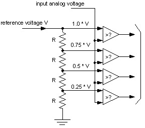
1It contains multiple isolated current-source. Block diagram of the voltage-to-frequency converter input of the left input stage has the potential VH the second input of the right input stage has the potential VL.

Voltage To Frequency Converter Using Ad654 Electronic Circuit Projects Electronics Circuit Circuit Projects
The output voltage and input frequency of the F to V converter is related using the equation V out V ref x C ref.
. The circuit topology of the current-source single-stage multi-input high-frequency-link grid-connected inverter is shown in Fig. The transformer is used to step down the 230V AC to 13V The LDO LM2940 is a 3 pin device into TO220 package. The circuits schematic diagram is shown below.
FUNCTIONAL BLOCK DIAGRAM BUF VDD CLKIN AD7740 VIN FOUT 25V REFERENCE VOLTAGE-TO-FREQUENCY MODULATOR GND CLKOUT CLOCK. AD Using Voltage To Time Conversion. Functional Software Electrical etc.
The FV converter basically consists of analogue comparator differentiator that detects the rising and falling edges of the shaped waveform voltage-controlled switch and output low-pass. Here the cycles of variable frequency source are. A frequency to voltage circuit diagram based on the TC9400 chip Frequency Conversion Conversion begins at pin 11 internal comparators non-inverting input where the signal input.
This frequency to voltage converter FVC can be used to turn your analog or digital voltmeter into a tachometer. The schematic for this AC-DC converter circuit is simple. Precision Voltage-to-Frequency Converters General Description.
LM231AN 25C T A 85C N08E DIP LM331N 0C T A 70C N08E. Ad Templates Tools To Make Block Diagrams. A voltage-to-frequency converter VFC is an oscillator Its frequency is linearly proportional to the control voltage.
The MAX1680 MAX1681 inductorless switched-capacitor voltage converters either invert an input voltage of 20V to 55V or double it while supplying up to 125mA output. The voltage vc is. The output voltage is also referenced to 62V in this circuit.
The voltage to frequency VFCcounter ADC is monotonic and free of missing. The Block diagram shows the basic voltage to time conversion type of A to D converter. The circuit consist of three.

Voltage To Frequency Converter Circuit Using Ca3130 Basic Electronic Circuits Electronics Circuit Electronic Circuit Projects

Frequency To Voltage Converter Circuit Diagram Applications Of Fv Converter Applications And Analog To Digital Converter Electronic Circuit Projects Circuit
![]()
Dc To Ac Inverter Circuit Working Limitations And Applications

Pin On Elektronika
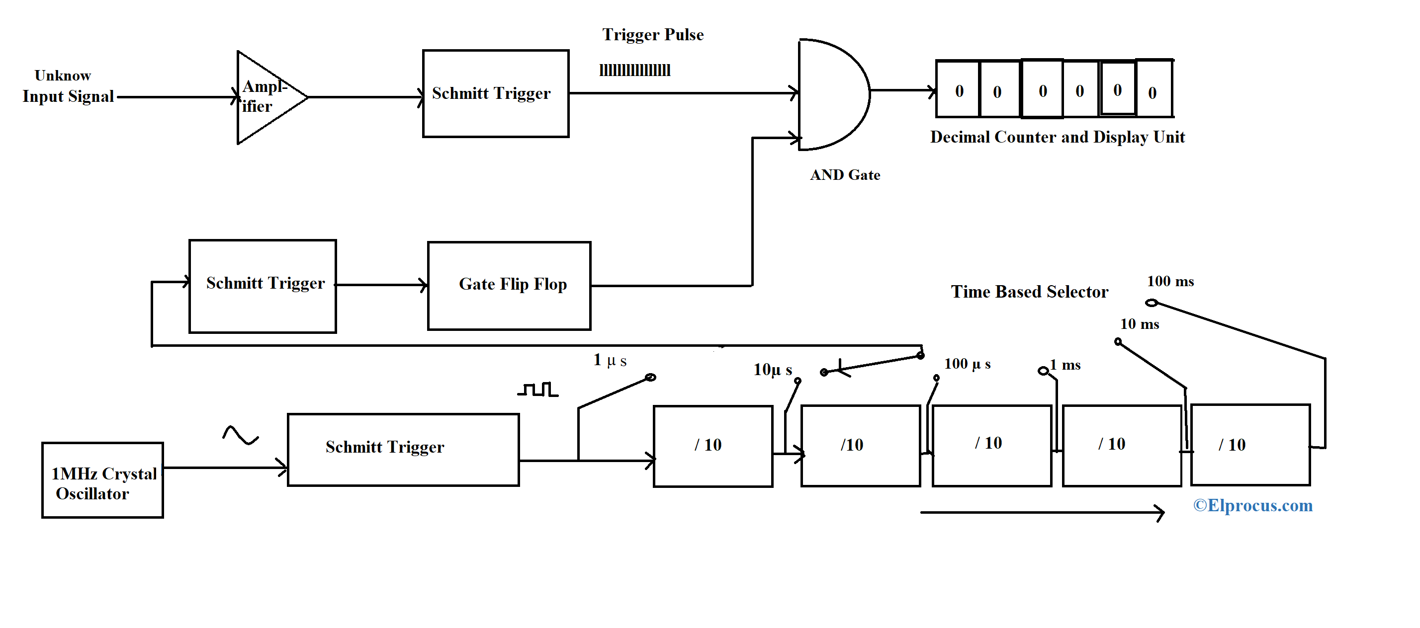
Digital Frequency Meter Construction Working And Its Applications
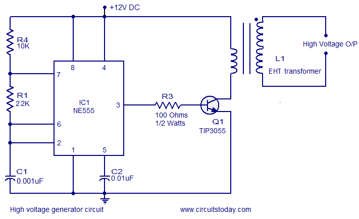
High Voltage Generator Circuit
How To Derive Obtaining Isolated Semi Regulator Outputs From A Buck Regulator Quora
How Do The Components Of A Dc To Ac Static Converter Combine To Produce An Alternating Current Quora

Voltage To Frequency Converter Circuit Circuit Circuit Diagram Electronic Circuit Projects
What Is The Process To Convert Ac To Non Pulsating Dc Quora

Uc3845 Current Mode Pwm Controller Pinout Feature Datasheet
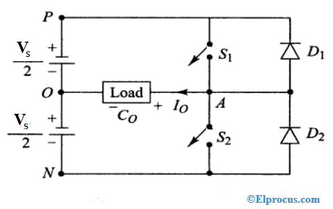
Half Bridge Inverter Circuit Diagram Advantages Its Disadvantages
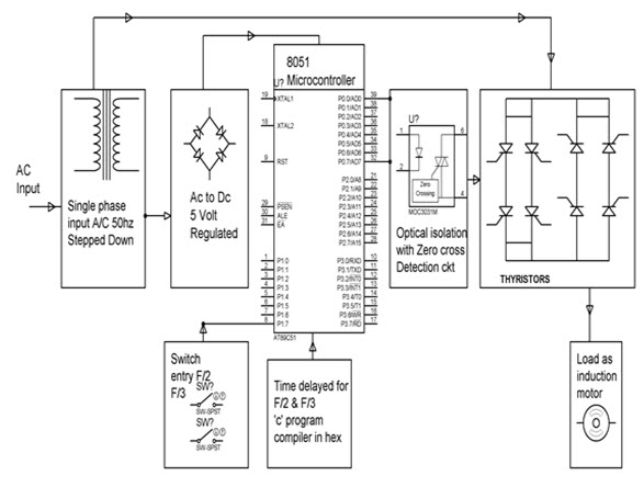
Buildig Of Single Phase Cycloconverter Using Thyristors And Applications
Variable Frequency Oscillator Circuit With Schematic
Analog To Digital Converter Block Diagram Types Its Applications
How To Convert Dc To Ac Quora
Frequency Counter Block Diagram Circuit Types And Its Applications